VFD Stuff
Vacuum Fluorescent Display
Also abbreviated VFD, this display tube that emerged shortly after the nixie tube, still is being used today. Though not as individual digits, or with a round tubular glass envelope. All modern VFD’s, are in flat planar glass housings. They come either as multi-character (and even multi-row) dot matrix displays, or custom for mass produced items.
I, and most old tube junkies, like the obsolete individual digit tubes, and the multi-digit tubes, that come in round cylindrical glass envelopes. The ones no longer made. Here is a link to Noritake, on how to operate VFDs:
It was extracted from an old Noritake databook, from decades past, but still applies. I also download, and posted it here, just in case Noritake removes it:
VFDs are basically directly heated vacuum tube triodes. The cathode and filament are the same element, and is set at some low value, but usually biased a few volts over ground. The heater voltage thru the filament is set just below the point where the filament glows. A VFD has many anodes, and these are coated with phosphor, and act as the light emitting segments. Anode and segment is used interchangeably. There are also be grids, just like in a ordinary vacuum tube triode. Difference, in this case, is that these grids usually have a positive voltage applied. This is done to accelerate the electrons to the anodes. Both anode and grid must have positive voltages on them, in order for that anode to conduct, and emit light, when its phosphor is struck. In fact, the grid usually draws more current than the anode segments.
In multiplexed operation, a grid is usually assigned to each digit, while like segments are tied together. When a digit is selected, a positive voltage is applied its unique grid, and the segments, that are needed to form the intended character. Unlike LEDs or Nixies, both digit and segment data are in the same phase (both positive), where as in nixies and LEDs, they are of opposite phase (one positive, one negative).
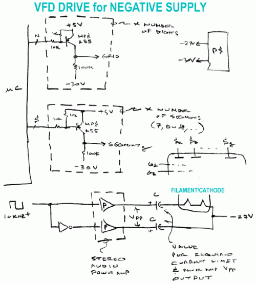
A little trick to simplify circuitry, is to use a negative VFD supply voltage. That way for a tube that needs 60V, make its anode and grids see +5V, and bias the filament to -50V. When the grid and anodes are OFF, let them fall to -55V. Here is a drawing illustrating this scheme:
No fancy driver chips are needed. It runs right off of common PNP transistors. Make sure they can handle the maximum extreme. A MPSA55 is good upto 60V (negative supply -55V max), and a MPSA56 is good to 80V (negative supply to -75V). Below is a filament driver scheme using an old, but still available, LM1877 stereo amplifier chip:
This chip was designed to put 1W of power into an 8 ohm load. That means it can deliver 350mA into the filament. Most VFD filaments are under 150mA. It can operate off of a 12V supply. Using some electrolytic caps, to isolate the DC, that AC wave can be shifted down to the negative supply level.
(Click on photo, below, to enlarge)
Here is the sole remaining VFD, I have from several used on my college senior project. This one, was an unused spare, purchased from C & H Surplus. I’m guessing it was around 1984, because that’s the year I graduated. Probably paid ~50 cents each for them.
End.


You must be logged in to post a comment.