Nixie Stuff
Animated .GIF Courtesy of Me.

Nixie Basics:
Nixies were once the most popular digital display technology in use. The coming of LEDs put a big crimp in their business, but at that time (70’s) LEDs weren’t bright enough to replace them. The LCD and VFD displays, however, proved quite readable in bright environments, and killed the nixie business.

(click on image to enlarge)
A nixie works in a similar manner as an LED. They are both current devices. That is they want to operate within a certain current range (current as in electrical current, measured in amperes, of milliamperes in this case; a milliampere is 1/1000 of an amp). Voltage is relatively unimportant, just as long as its high enough to initiate conduction. For a nixie, that’s called the strike voltage and is normally guaranteed to be at 170V maximum. So supplies of 180V or somewhat higher (up to 200V) are commonly used. Once the nixie strikes the voltage, from anode to cathode, drops to its sustain value. This is usually in the 130V to 150V range. An anode resistor is placed in between the supply and anode, to limit the current. Nixie tubes usually see currents from 1mA to 3.5mA, for small nixies (0.6″ digit height max), and 4mA to 8mA for larger devices. The anode resistor takes up that difference, between the supply and anode, and the current can therefore be calculated by using Ohm’s Law. See formula in drawing, above, for Ia. It’s basically that voltage difference divided by the resistor, Ra. If this resistor were missing, the nixie would still like to drag the 180V supply down its sustain level. With typical nixie supplies, that would finally happen when the supplies maximum is reached. Normally, 25 to 60mA. This will not kill the nixie, immediately, but will age the tube quickly, and it will die within a few hours. If you are using a bench supply capable of delivering “amps”, at this high voltage, then that nixie will disappear in a flash (literally).
LED’s work, the same way. Only they have a Forward Barrier Junction Voltage to overcome. Unlike the nixie’s Strike/Sustain level, once conduction starts (in an LED) the voltage levels off. It does not drop to a lower value. But the need for a series resistor (to limit current) still applies.
Nothing Turns-ON Instantaneously: (click on image to enlarge)

This is scope photo, of a nixie being multiplexed. The two traces are of the anode voltage, and the cathode current. When voltage is applied, it takes some time for the nixie gas in the tube to form an ionized plasma, and conduct current. For nixies this is between 10 to 50uS (0.00001 to 0.00005 seconds) typically. Before conduction the anode sees the full supply voltage (190V in this example). Conduction, once it starts, occurs gradually (~10uS in this case). The anode voltage drops during this time (in phase), due to a required anode resistor inserted between the supply and the nixie’s anode. This is not to be confused with overshoot (of an underdamped system). A nixie is not a reactive component. There is no initial surge. As you can see, the current actually rises rather slowly (relatively speaking).
If you multiplex a nixie, you need to add blanking intervals, to avoid ghosting. Ghosting is one tubes data interfering, visually, with its neighbor. Typical blanking intervals, for nixies, are between 100 to 300uS. Blanking is done, by turning ALL anodes OFF. In normal multiplexing operation, the intended digit is turned ON, by lowering its cathode to zero volts, during the blanking interval. Only one cathode ON, at any time. At the end of the blanking interval, the intended anode is turned ON. It should be ON for a display interval between 1mS to 4mS (0.001 to 0.004 sec) . A typical multiplexed frame is: B-H10-B-H1-B-M10-B-M1-B-H10… This is an example of a 4 digit clock display, with B=blanking interval, and H10=10-hours digit, and so on (M10=10 minutes, M1=1 minutes). The total frame time should be less than 20mS, to avoid flickering.
DO NOT blank, by turning all cathodes OFF. Especially, when using cathode drivers like a 74141 (or its Russian equivalent). If you attempt this with these devices, they will see over ~100V, and will conduct thru more than one cathode at a time. This will look similar to ghosting. These devices are leaky, so at least one cathode should be ON at all times.
Turn-ON time decreases as supply voltage increases. Use a higher supply voltage when possible. Just because the specs say 170V, doesn’t mean you need to use 170V. This is a minimum value, to ensure striking. Remember that anode resistor. Its REQUIRED ! When a nixie turns ON, the voltage drops to its sustain level (130V to 150V). The difference (Supply – Sustain) is dropped across that anode resistor. That sets the operating current. Use a supply of at least 180V. 190V to 210V is even better, if its a multiplexed circuit.
MC34063 Based Nixie power supply:
Powering your from low voltage sources, such as batteries, or wallcube transformers:

Click on drawing for better resolution.
Notes:
1. All resistors 1/4W, 5% Carbon Film. R3 & R4 1/4W 1% Metal Film.
2. L1 – Bourns SDR1806-221, SDR1307-221, Murata 18R224C, API 4590R-224K, Coiltronics DRA127-221-R, DR127-221-R, UP4B-221-R
3. Q1 – IRF740A or B, IRF644, FQP16N25, STP17F25, or BUZ73
4. D1 – BAV21, UF4004, UF4007, MUR140, or MUR160
5. C1 – 220uf, 25V Low ESR. 0.3 ohms or Less.
Parts available at Mouser Electronics
D2 and Q2, form active pull-down. This allows Q2 to discharge Q1’s gate charge much faster, than R2 (1K) can do by itself. Effectively making it look like a 10 ohm resistor. But only when swinging down. Swinging up, turning ON Q1, then Q2 is out of the picture. The beauty of active circuits. Efficiency can be as good as 80%. This circuit can deliver close to 45mA (180V out), with 12V in.
You can get voltages other than 180V, by adjusting R3, or R4, or both. See formulas on drawing. 250V max with components shown. Need higher, see below:
Adding Multiple Voltages:
You can get multiple voltages out of this supply (MK1.5), and most any other nixie supply, by adding multiplier ladders. What’s required is that you have access to the Pulsed Output. If so, you can get the voltages in the drawing, below:

Click on drawing for better resolution.
Note, you can get both higher positive voltages (+360V & +540V), and negative voltages (-180V).
If a voltage isn’t quite right, you can always fall back on your early electricity classes. Thévenin equivalents, can be used. Suppose you need +450V, and the anode resistor is 680K. Make a divider, and hook it up to the +540V supply. The divider will output 450V (unloaded) if you pick 820K, and 3.9M. Also, they look to the anode, like a 680K resistor, since 820K in parallel with 3.9M, is 680K. Here’s a reference to Thévenin, if you need more convincing.
IF ITS TOO SIMPLE – AVOID:
Avoid “passive pull downs” like the circuit below:

In this circuit (MK 1) , the MC34063 can only actively pull-up (and turn ON) the FET’s gate. Turn-Off is only thru R2 (330 ohm). Turn-Off is critical, because that’s when the high voltage pulse is generated. You want that as quick, and clean, as possible. This simpler MK1 circuit can only deliver ~10mA, before the FET gets too hot. Poor efficiency (under 60%). The MK1.5 circuit can deliver close to 45mA, at an efficiency near 80%.
TI (Unitrode) UC3843 Based HV Supply:

Alternate chip to the MC34063. The UC3843 both sources and sinks the FET (Q1). No other drive components needed. On the down side, it needs at least 9V to work, and has internal shutdown circuitry, that switches it OFF, if the input voltage gets too low.
Discrete HV Power Supply:
Here is a HV supply, that uses only discrete components. No ICs used:
(click on Drawing to enlarge):

Regulation is poor, relative to IC based supplies, but adequate for nixie use. It is also less efficient than most IC based power supplies, but comparable to 555 based designs. Maximum recommended output is 15mA.
Its based around an astable multivibrator, using PNP transistors. Regulation is performed by varying the duty cycle, by varying the RC time of R4 & C4. Q4 acts as a current source for charging C4, and varies with the output voltage. The higher the voltage, the shorter the period that the MOSFET (Q5) is ON. Q3 is also added to speed up the discharge the MOSFET’s gate.
Low Cost “FET-less” HV Supply:
Mostly all boost type HV switching supplies are reliant on modern power MOSFETs to act as efficient switches. Though these supplies are relatively inexpensive, the MOSFET usually represents the most expensive component in the supply. Often,even more than the controller IC. To really make a cheap supply if only a couple of milliamps of current is needed, here is a design that uses less than a dollars worth of parts (as of mid 2019):

It can deliver upto 4mA, without heating up a common MPSA42 transistor used as the “switch”. A common base hookup is used for the A42, so faster internal switch of the MC34063 is also in series with the primary current path, since a MPSA42 is a pretty slow transistor. Two common (but very fast – 4nS) 1N4148 diodes as the HV rectifier, and hooked up in series to double the final reverse blocking capability to 200V. The 2mH coil and MC34063 are the most exotic parts in this design, though both can be easily found.
Its something to keep in mind, if not much current is needed.
Demise of Fry’s & Radio Shack & Buying Parts Locally:
Now, pretty much all parts need to be “mail ordered”, online. But there’s one part, that can be had locally, at a decent price. Those are 24VAC transformers, which are carried by ALL HVAC (Heating, Ventilation, & Air Conditioning) suppliers. Usually in the $12 range (as of late 2019). They are commonly rated for 30 or 40VA, and can accommodate 120V, 208V, and 240V AC lines, such as the White Rogers 90-T40F3.
Given that the voltage is still relatively high, a few multiplier stages are only needed to boost it up to just over the requisite 170VDC, used by nixie tubes:
(click on drawing, to enlarge):

D1 & C1 are required to get DC from the 24VAC. Depending on the low voltage requirements (5V logic or uC supply), several choices for dropping the ~36VDC to 5V are available, from Zeners, to linear, & switching regulators. C2 thru C5, and D2 thru D5, are needed to get the 170V+ HV supply to drive the nixies. It was found that using a 40VA (24VAC) transformer & 1000uf capacitors, a voltage over 170V can be had, that still can deliver upto 70mA. With no load the HV was closer to 190V, and dropped just 170V, with a 70mA load. Note, that this was measured with a meter, that averaged that reading about the ripple. Any ripple peaking over 170V will strike the nixie tubes.
For a more compact supply, a switchmode converter may be used. I modified one of my NK01 supply kits:
(click on drawing, to enlarge):

From the drawing, you can see, that the current, to be boosted, thru the coil, connects directly to the rectified & filtered output (VD) of the 24VAC xfmr. The rest of the switcher gets a lower voltage (12V), by way of a zener & resistor. This is because most MOSFETs can not handle a gate (to source) voltage exceeding 20V. Also the coil value was doubled, and the switching frequency increased, to accommodate the higher input voltage. This compact supply exceeds the output of the multiplier circuit, and can easily output 100mA (16.5W), without warming up the parts, too much. 120mA (20W) was also achieved during testing, but that may stress the unit in a long term application, in an enclosed environment. The increased output, is due to the need to only boost the voltage 5x (36V to 180V), as opposed to 15x (12V to 180V), as commonly used.
Simple Hours Section for Discrete Direct Drive Clocks:

Click on image to enlarge

Click on image to enlarge
Simple One Second Time Base:
The line frequency from your household AC power, historically, has been kept accurate, so that old motor driven clocks maintained proper time. During daylight hour, the power frequency lags, due to the heavy demand. The power company, to compensate, speeds up the generators, during the wee hours of the early morning, to catch up. They make sure that exactly 5,184,000 cycles (in 60Hz areas), or 4,320,000 (in 50Hz territory) occur in a 24 hour single day.
Here is a simple time base circuit, using a single 4000 series CMOS 4518 Dual BCD counter chip:

If your nixie clock’s power comes from an AC wallcube, or other stepdown transformer, you can tap one of the AC leads going into your fullwave bridge, as shown in red (existing power supply circuit), and purple (signal conditioner). One BCD stage of the 4518, divides the 50 ro 60Hz, by either 5 or 6, to get 10Hz. Then the second stage futher divides it by 10, to get a 1Hz output.
To make the first stage divide by either 5 or 6, the counter is reset to zero, when it reaches the max count. Here its done using an AND gate made simply from two diodes, and a resistor. The counter is reset, when The reset input (R) sees a logic one. This only occurs when a binary count of ‘5’ or ‘6’, occurs, depending on how the jumpers to D3, are hooked up. To QA, for div-by-5, and QB, for div-by-6.
The purple section, converts the AC half wave, from one of those taps, to a clean square wave pulse. R1 is needed, as the AC comes to its zero crossing, and drops between the forward drops of it rectifiers, the impedance goes to infinity. If a resistor was not present, Q1 would turn off slowly, and output would also rise slowly. R2, R3, and C2 suppress noise spikes from creating extra, unwanted pulses. Q1 can be any small signal NPN, such as a 2N2222, 2N3904, or whatever you have in your junk box.
The Infamous “Blue Dot”:
Mostly seen on the Russian IN-18 nixie tube, when displaying the numeral “1”, there appears a small glowing blue spot of gas, just in front of the digit. Its sometimes seen in other tubes, and usually the larger ones. Back when these tubes were used in instruments, it wasn’t an issue. The display usually had a transparent red plastic filter in front of the tubes, so the blue glow, if present, was blocked by the filter. The filter would only let red light thru.
A cause for this phenomena to happen occurred to me when I lit up a much smaller and, then, more common NL-841 nixie. I used its decimal point as the anode, and this resulted:

Since the decimal point makes for a very small anode, all the current that makes the digit glow must also pass thru it. This means the blue glow happens when the current density exceeds some particular threshold.
I ran an experiment with a few of my IN-18 tubes, trying to see, if I could reproduce the blue dot. Below is my circuit:
Many, if not most nixie clocks use the 7441, 74141, or its Russian equivalent ICs, to drag the desired cathode to near ground potential (zero volts), to turn it ON. Simple open-collector transistor stages, which have the collectors of the 10 output NPN transistors tied to their respective nixie cathode (0-9). The emitters of all 10 transistors are tied to ground. Some simple logic turns ON only one of these transistors at a time, which allows the selected cathode current to flow to ground. The remaining 9 “off” cathodes, an connected transistors float to some random voltage. Ideally they should go up to the anodes voltage, so the voltage difference between the anode and “off” cathodes is zero. Fortunately, there needs to a significant voltage difference between the anode and cathode, for current to flow, for it to glow. Usually between 130 to 150V. That means if the supply is 170V, then cathode only needs to rise to 40V (170V – 130V), to stay “off”. Nixie driver ICs, of the day, usually had zener clamps around 65V, because high voltage transistors did not exist (or at economical) at that time.
But my experiments found that even though, the “off” cathodes, stayed off, they still drew a small amount of current. This altered the current flow pattern inside the IN-18 nixie tubes, changing the current density, in all areas of the tube. But most notably when the “1” numeral is lit. It makes a narrow current channel to the anode, and the off cathodes may be acting as beam forming plates, as in beam power tubes, like the 6L6.
Here are the results of varying the off cathode voltage, Vk:

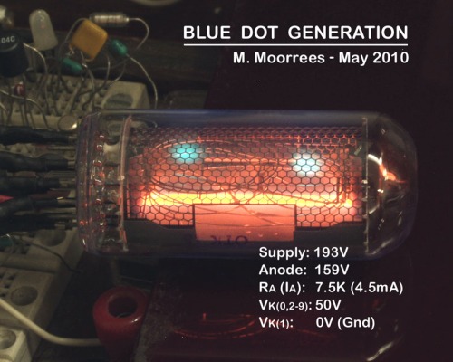

The blue dot could be created at will. More so, the lower the voltage is, on the off cathodes (Vk). The solution, is very simple. Use cathode driver transistors, that can rise to above 90V. Now common transistors like the MPSA42, and 2N6517, will do the job. Also make sure, your mid-pull voltage is between 90 to 110V.
Lower Voltage Cathode Drivers:
The blue dot experiment did make me wonder, how low could the cathode voltage be clamped, and still be an acceptable nixie driver. So again, I rigged a test circuit, very similar to the blue dot circuit, but with a transistor buffer, to present a lower impedance, which would be simulate a zener diode:
I used a smaller, and much cheaper IN-8-2, for this experiment. Since its small, and uses much less current, there should be no blue dot issue. I varied the voltage from 10 to 75V, and observed the glow. Below 30V, and especially below 20V, the other cathodes started to glow orange, and it was harder to see, which was the desired numeral to be on. Over 40V, the results where quite acceptable. Here is a composite photo:
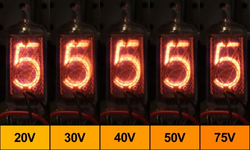
In real life, the difference is much greater. In the past, I’ve used drivers like the TI SN75468, which can handle upto 100V, but the test results show that an Allegro ULN2003 (50V max), can also be used. Both these chips contain 7 open collector darlington drivers. They were originally made to drive solenoid hammers, in old dot matrix printers. They are pin-to-pin compatible with each other. The only difference is that the SN75468 can tolerate a higher voltage.
Here is how the zener clamp is to be implemented, when a ULN2003 is used:
Biquinary Nixie Tester:
Biquinary nixie tubes are special nixie tubes that only need 8 connections to display any of the 10 characters (0-9). There are only 2 types of these tubes with the same pinout. All these tubes have a common miniature 9-pin base. The same base used for tubes like the 12AX7. So sockets for these tubes are easy to find. The two types are (1) the Burroughs B5025, which was second sourced by National, as the NL5025. The B5025 (and NL5025) have a 130V strike voltage, 40V lower than the typical 170V, for the grand majority of nixie tubes. The second type is the (2) Philips ZM1030 & ZM1032. The ZM1030 and ZM1032 are the same tube, with the only difference being that the ZM1030 glass body is painted red (“nixie orange”), while the ZM1032 is left unpainted. The ZM1030/ZM1032 have the normal strike voltage of 170V. The other difference between the B5025 and ZM1030/32 is that the ZM1030/32 is mercury enhanced, where as the B5025 is not. Mercury greatly increases the life of the nixie tube. Often 10x or more.
Below is a circuit for testing these tubes:

As you can see in the drawing above, these tubes have 5 cathode connections, and two anode connections. Two cathodes are connected to a single pin (01, 23, 45, 67, 89). The actual cathode shapes are arrayed into two groups. The odd group (1,3,5,7,9) and even group (0,2,4,6,8). Each group is surrounded mostly by either odd or even anode. A screen pin is connected to a mesh, that separates the two groups, and is tied to Vbs.
To light up the desired numeral, its respective cathode is grounded (tied to 0V), and its respective anode has the strike voltage applied thru a current limiting resistor (R10 or R11). For example, if “5” is to be displayed, ground cathode 45 (S3-3 is on), and the ODD/EVN switch (S2) is put in the “Odd) position. In the circuit, above, the inactive anode it pulled down to a voltage below the “sustain” voltage, and should never be brought much below half of the strike voltage.
There are two mid-pull levels used for these tubes. One is for the screen (Vbs), and the other is for the unused cathodes (Vkk). Vbs can be anywhere from 1/4 to1/2 of B+. Vkk can range from 1/4 to almost 2/3 of B+. Note that these levels overlap, so it is possible, for simplicity, to just use one level for both. Two dividers are shown in the circuit, since the ZM1030/32 specs show that ranges are different, and by experiment, I’ve found that levels can be at the extreme ends from each other, with no ill effect.
Neon Bargraph Winker:
Something to do with Russian neon bargraph tubes. This circuit is for the IN-13, which uses less current than the IN-9. It has two sections. The first section uses uses a LM393 comparator chip to generate 140V. Half of the chip is a pulse generator, for pulsing the power FET (Q1), to make the HV. The other half, monitors the voltage, and inhibits pulse generation, when the desired voltage is reached. The second section is a phase shift oscillator made around Q2, a common PNP transistor. The phase shift oscillator controls the current thru the bargraph tube, thru Q3. It does this by making the voltage across R11, follow the sine wave. That means the current thru R11 is also a sinewave, which is the same as the collector current (almost the same, but close enough for government work). The collector current is the same current that flows thru the bargraph, and there you have it.
Click on schematic to enlarge:

Click here to see the video of the winker working.
General Russian bargraph data:

Note: Both IN-9 and IN-13 have a circular diameter of 9,5mm (~3/8″).
Nixie – Article at Wikipedia.
Click on images to enlarge:

No such thing as a green nixie. This is a composite photo of two ordinary orange nixies. A little Photoshop magic of the color settings, and then you have a little April Fools joke.

Radio Shack once sold nixie tubes. Only for one year though. Sold VFD displays, too. The 11-18mA operating current, for the nixie, is an oversight by Radio Shack. 11-18mA, is the peak current, if the tubes are multiplexed. 1.0 to 2.5mA is more appropriate for this nixie type, for continuous operating current, or the averaged level, if multiplexed.
Supplemental Nixie Documents
3V Nixie Clock – 4 Digit nixie clock powered from 3V battery
Low Voltage Nixie Supplies – Design ideas for nixie supplies with 5V or less input
Power FET Primer – Philips guide to using power MOSFETs. Take a look at p57 for something familar.
End.

You must be logged in to post a comment.